A typical logic circuit problem will give you a logic circuit to analyse. A common question might be something like this one:

In this case, you’ve got to work out what the final output of the logic circuit at the far right is. What you need to do is work your way bit by bit through each part of the circuit.
So if we start with the top NOT gate – it has just one
input – x. So the output is going to be ‘NOT x’, or  in logic notation.
Moving down to the middle connector on the left – the OR gate – it has 3
inputs, x, y and z. So the output of this gate is going to be
in logic notation.
Moving down to the middle connector on the left – the OR gate – it has 3
inputs, x, y and z. So the output of this gate is going to be  . The bottom
left gate is an AND gate – but be careful. The inputs are not x, y, and
z. They’re actually, x, x and z – the x is input twice. So the output
is going to be
. The bottom
left gate is an AND gate – but be careful. The inputs are not x, y, and
z. They’re actually, x, x and z – the x is input twice. So the output
is going to be  .
After having done this much, we can put this information into our diagram:
.
After having done this much, we can put this information into our diagram:
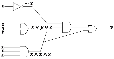
We can move to the next stage of the logic circuit
now. There are two more gates – an AND gate with three inputs, and an OR gate
with two inputs. However, if you look at how everything is connected, you can
work out that you can’t do the OR gate until you’ve done the AND gate. This is
because the output of the AND gate leads directly into the OR gate. So let’s
do the AND gate first. It has three inputs – , and . So the output is going to be:

Notice how I’ve used brackets to keep each of the
inputs separate in the expression for the output. Because the inputs
themselves are logic expressions (for instance the input), they need to be
evaluated first. That’s why we use the brackets.
This output from the AND gate is one of the inputs into
the final OR gate. The other input comes from the output of the bottom left
AND gate – .
So after feeding these two inputs into the final OR gate, we should get:
